
Floppy Disk Emulator Network System
Description and Instructions
(C) 2009-2018 PLR Electronics

Overview
The USB Floppy Network system is designed to download data to many floppy emulators from one central computer. It does not need a USB stick although each floppy may still accept USB sticks as usual.
The transfer software allows individual or combined control of 32 floppy drives from one serial line. You may add or delete files on each device or every device. The system is expandable up to 64 devices.
To use this system, you must have the following:
- One or more network capable USB Floppy devices
- The network RS-485 Converter unit
- A Windows computer with a COM port
- The network transfer software
- Ethernet cable, CAT-5 is acceptable
- Ethernet junction boxes or splitters for each additional USB Floppy device
PLEASE NOTE: The standard USB Floppy device is not compatible with this system, you must use a network capable device.
ALSO NOTE: The system is for one-way communication with the floppy drives only. It may write or delete, but may not transfer files back to the host computer (as of software version 2.0).
What’s included
The following items are part of the network converter order. You only need to order one per host computer. The actual USB Floppy device(s) must be ordered separate. Up to 32 drives may be controlled from each network converter box, and you may control two converter boxes from the software.
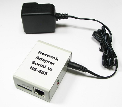
One Network communications adapter. This plugs into your Windows computer through the 9-pin cable shown below. The power supply is included and is compatible from 100V up to 240V. The plug is american standard and may need an adapter (not included).
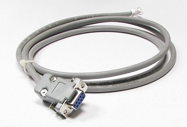
This serial cable plugs into the 9-pin RS-232 port on your computer, usually designated as COM1. If you do not have a serial port, there is an included USB-to-serial adapter (not shown).
The network transfer software will be downloaded upon purchase. We will email the download location.
Ethernet/CAT5 cables are not included. Please use standard 8-pin cabling, do not use crossover or patch cable.
The CAT5 splitter devices are not included. These are needed to use more than one floppy drive. If you only have one drive, then you can plug the CAT-5 cable directly. You will need one 8-pin splitter for each additional device. The idea here is to daisy chain all eight lines; if you cannot acquire splitters but have the expertise, you may splice and branch the eight lines in a hard wired manner. It’s recommended however to purchase, do a internet search for “CAT-5 splitter”
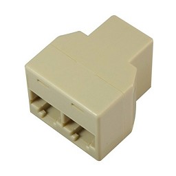
You can not use any Ethernet hub or other such Ethernet box; The system uses RS-485 protocol in the cabling, not Ethernet protocol. Use CAT-5 splitters.
Installation
Software installation
Download the program and run the the Windows installer. When finished, this will add several shortcuts to your menu or desktop. Use the shortcut called RP_NTFS_ENU, and you may delete the other two shortcuts.
Warning: be sure that your Windows computer has COM1 enabled or the software will not operate!
The transfer software will ask you to LOGIN each time you start the program. Right now there are no users so you must use the administrator password, username: aaaaaa, and password: aaaaaa.
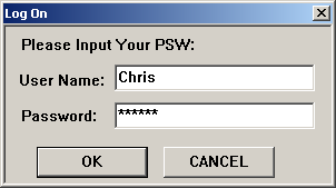
Later you may change the password or add other user accounts.
Main screen
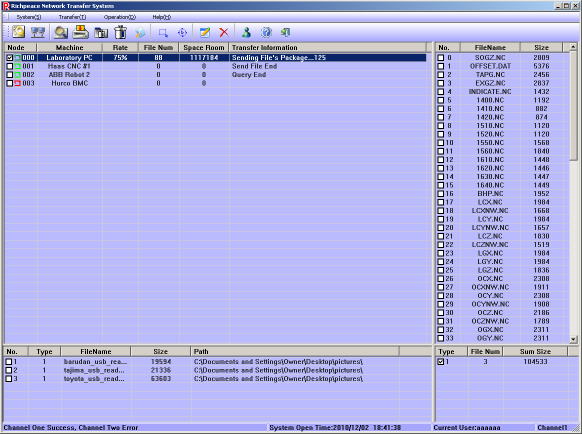
After password and loading, you will now be at the main screen. A diagram of the main areas is shown below.
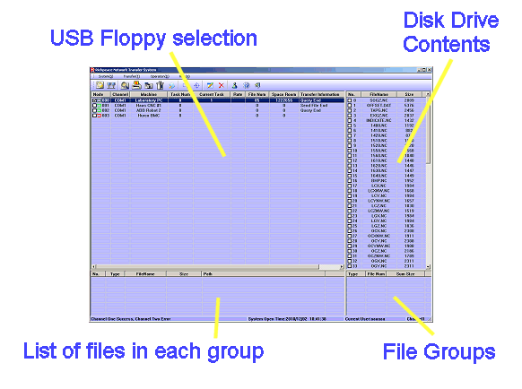
- USB Floppy selection area: This is where you choose which network floppy drives will be used.
- Disk Drive contents: If you update or query a drive, this will show the list of files on the drive.
- File Groups: When you are uploading files, you do it in groups and must select at least one group.
- List of files in group: Each group can have one or more files in it. When you click on file groups, this windows will show the group contents.
Configuration
The default screen will be cluttered, so we will configure the software to clean it up. Choose the SYSTEM menu at the top left.
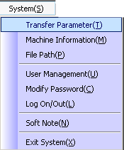
Click to enter the Transfer Parameter menu, first.
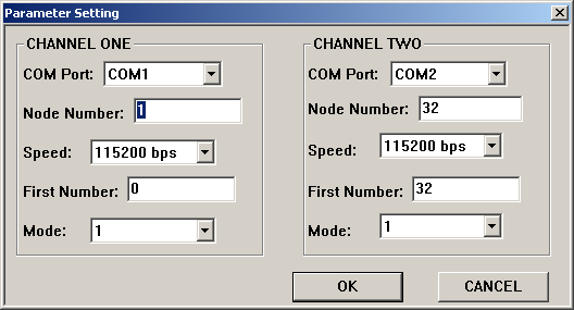
There are two channels here, depending if you are using one or two network communication adapters with your computer. If you have less than 32 floppy drives, then you are only using one Network communication box and will not need channel two.
Please set the parameters now, per below instructions.
COM Port: If your network adapter is plugged into some other COM Port besides COM1, then change it here.
Node Number: Here you are entering the total number of USB Floppy devices you will install. Put this number in the left box, the channel one Node Number box. In the channel two Node Number box, put zero.
Speed: Leave speed at 115200 bps.
First Number: Please change first number to zero. It will be less confusing when configuring your USB Floppy hardware dipswitches.
Mode: Leave at 1 for now. When your system is working, then you may change the number; higher numbers increase communication speed.
Hit OK when done.
Machine naming
You may optionally give names to each of your USB Floppy units. Look at the below picture for an example:
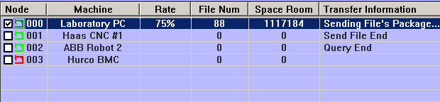
The Machine name makes it easier to understand which unit is being controlled.
To set machine names, please go to the SYSTEM menu at the top right and choose MACHINE INFORMATION
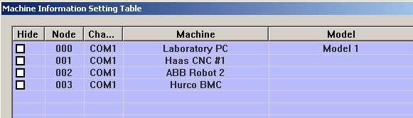
When you are in the machine setting windows, double-click on the Machine column for each USB Floppy device. You may optionally add information to the MODEL column but this will not be displayed. Please limit the amount of characters in the name.
Software configuration is done! The main screen will be a lot less cluttered once you removed all unnecessary numbers. You will want to look into USER MANAGEMENT to add some user name besides aaaaaa.
Next is hardware configuration.
Hardware Configuration
The network version of the USB Floppy uses internal dipswitches to set its unique ID number from 0 to 31. The other, non-network USB floppy models use these dipswitches for a different purpose, for electrical interface configuration. Because the dipswitch flexibility is lost, the network version is less compatible; please contact us to see if the network model is compatible with your machine, or can be made compatible.
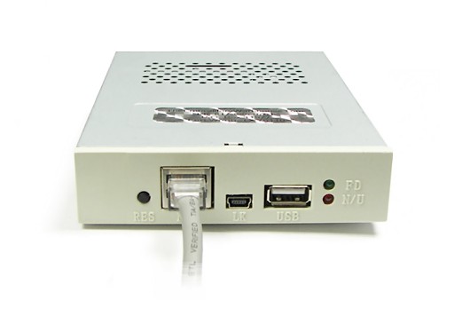
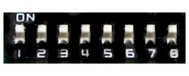
The dipswitches are located on the top of the unit, as per below picture:
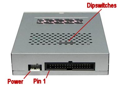
The dipswitches are numbered 1-8, and one side of the dipswitches will say ON.
There are two common network drives, the IBM and SW network drives. Their ID locations are in different locations.
IBM-Network drives: The ID combination for the network system uses dipswitches 1-5 and set as follows:
- ID #0:: (1 2 3 4 5) ON ON ON ON ON
- ID #1:: (1 2 3 4 5) OFF ON ON ON ON
- ID #2:: (1 2 3 4 5) ON OFF ON ON ON
- ID #3:: (1 2 3 4 5) OFF OFF ON ON ON
- ID #4:: (1 2 3 4 5) ON ON OFF ON ON
- ID #5:: (1 2 3 4 5) OFF ON OFF ON ON
- ID #6:: (1 2 3 4 5) ON OFF OFF ON ON
- ID #7:: (1 2 3 4 5) OFF OFF OFF ON ON
- ID #8:: (1 2 3 4 5) ON ON ON OFF ON
- ID #9:: (1 2 3 4 5)
The list continues to #31 in the binary notation (inverted). It is recommended that you set your first network USB drive to ID #0.
In parameters, node number should be 32 for IBM-network drives, and first number should be zero. However if you only have one drive and it is set for ID #0, then you can use node number 1 and first number zero to reduce the number of unused drives shown on your screen.
SW-Network drives: There are only four ID combinations (in SW-Network models released after October 2012). The new ID combination for the SW network system uses dipswitches 6-7 and are set as follows:
- ID #0:: (6 7) ON ON
- ID #1:: (6 7) OFF ON
- ID #2:: (6 7) ON OFF
- ID #3:: (6 7) OFF OFF
In parameters, node number should be 4 for SW-network drives, and first number should be zero. However if you only have one drive and it is set for ID #0, then you can use node number 1 and first number zero to reduce the number of unused drives shown on your screen.
You may change the dipswitches while the USB drive is live, if you press the black reset button on the front of the USB Floppy unit after each change.
Do not have two devices with the same number on the same network line.
Do not use an ethernet hub or any other powered ethernet device to extend the line. This system uses the ethernet cable but not the ethernet protocol. Only use RJ-45 splitters.
Double density or high density mode
Dipswitches 7 and 8 together set the size and data rate of the floppy drive between 720kb and 1.44mb. Your host machines may or may not be able to use the high density 1.44mb size, so always try in 720kb mode first until you know the system is working, and then you may experiment with HD mode.
- 720kb mode: (6 7 8) ON OFF OFF
- 1.4mb mode: (6 7 8) ON ON ON
Installation and Operation Videos
Please view these full screen! The button at the bottom right of the viewer should do it!
USB Network Video 1: Installation and Setup
USB Network Video 2: Operation
Download
To download the transfer software please CLICK HERE
(C) 2009-2018 PLR Electronics