USB Floppy Disk Drive EmulatorTechnical documentation, Troubleshooting, and Configuration(C) 2009-2018 PLR Electronics  Table of Contents1. Theory of Operation Theory of OperationReview of the floppy disk as a storage medium, and the USB replacement In reality the floppy disk is an analog device that is used to store digital data; in any situation involving analog recordings, the data size can quickly get out of hand depending on how perfect you want to reproduce it. An example would be an uncompressed recording of a song; it quickly gets into the tens and hundreds of megabytes, even though one song is only minutes long. In this case, the magnetic platter of the floppy disk is only used to store digital data; the 1’s and 0’s are easy to convert, but the time stamp and duration of each bit can vary infinitely on the continuous analog track. In short, floppy disks not only hold the digital data but time domain data as well. The result is that, to represent a standard high density 2 megabyte floppy disk, you may have to use alot more than 2 megabytes; unless you start interpreting the data and storing what you think is important, and in a more convenient and compact form… meaning you discard and lose original data (in this case, time domain data) in the process, saying that you can reconstruct it “good enough”. Or basically, the USB Floppy has the ability to extract DOS files from the “raw magnetic data” that the host system feeds it, and then copy these extracted DOS files to a FAT16-based (or FAT32) USB storage device, and vice-versa. Meaning lots of convenience, that files appear and can be read from your USB stick as if it really were a floppy disk, that you can just stick it in Windows, drag and drop, and then move the USB stick to your CNC machine or whatever, and it sees the recently added files as if they were on a floppy disk all along. There are no special formatting needs, and no buttons to push. For instance, at the top level of data, we encounter machinery that, for whatever reason, do not use the DOS-style FAT12 file system format that has become so popular over thirty years that it became a de-facto standard. This means that some machines formatted their floppy disks in a way that would not be readable in a DOS or Windows operating system, because Microsoft chose to be very limited in what kind of filing formats they would support. And, back then when your machine was designed, compatiblity with Windows was very low on the priority list, Microsoft’s Windows likely not having been invented yet. At a lower level, a system designer in the 1980s could have chosen to store the data packets in a non-standard way; this is what the Amiga designers did. Forget reading files in Windows, and your PC is not likely to even be able to load sectors of data at all without help. And this means different interpretors are needed for this. At a lower level than that, a designer could use different data rates or different encoding methods on the 80 tracks, or even mix which tracks get what kind of encoding method (some designers did). Even more interpretation difficulties for the USB Floppy emulator. In other words, start with the format that 90% of computers and machinery already use and which is fully compatible with each other and with every Windows computer. After that, then work down into the custom jobs, one class of machines after another. There is a model released (the 2-SY) that has the option to ignore the top-level FAT12 interpretor, which should provide compatibility with a good percentage of the custom systems; the non-FAT data for the entire disk is stored in one file with a .IMG suffix (standing for uncompressed disk image). Other systems, such as the Amiga gaming console or musical keyboards or whatnot, and really old industrial machinery that was developed before there were any strong standards, will be on the list somewhere down the road Again, the other choice is to have really huge floppy disk image files (in the tens of megabytes) just to hold 720kb worth of data; because while every floppy is physically about the same, the structure and timing of how information was stored is machine or designer dependant, and to have 100% compatibility means we have to store every bit of information possible, logical data, timing, any other funny behaviors such as using more than 80 tracks, everything. The majority of our customers do benefit from the convenience of the FAT12 interpreter (no software needed!), and so we ask patience for those with custom systems, and even ask for help; having data on your custom format, in the form of documents or a non-standard floppy disk shipped to us, goes a long way to getting a solution out faster. Please contact us in this case, if you foresee this becoming a great need in the next year or so. Floppy drives aren’t dead but are well on their way… Floppy drive electrical interfaceThe floppy disk drive hardware itself was designed in various ways in an effort to help the floppy drive controller chip designers use their brand or model of drive effectively. And more than one type of floppy control chip were released to the market, and more that one idea how one should go about helping these chips were used. This means that several different interfaces and behaviors appeared over the years, meaning that floppy drive hardware are not that interchangable depending on the abilities of your host system. Meaning the USB Floppy is not going to be 100% plug-and-play for all customers, unfortunately. There is going to be some amount of configuration to be done per machine model unless we are familiar with your model through enough sales and customer feedback. We have some customer feedback now (edit: as of 2016, a LOT of feedback!) so we have a good idea how to do all the configuration for you. At the same time we bring up the existance of floppy disk drives larger and smaller than the now-ubitiquous 3 1/2 standard PC floppy drive. Physically different. Half size, 3/4 size, double size. And also of connectors and plugs that are not the standard 0.1″ spacing 34 pin rectangular connector, but instead have different amount of pins or use a flat flexible ribbon cable. This means we must match the size and shape of the floppy drive, then match the connector, then match the data interpretation abilities of the unit, to make any given customer satisfied with his device. Which is why we will generally ask the make/model of floppy drive, the make/model of host machine, and also we ask for any details that will help us guesstimate what you need in case its a machine we do not know; at the very least, is it using a format compatible (readable) with Windows. As mentioned, matching the electrical layout is something that must be done before the machine even realizes there is a working floppy disk drive in place. In order to match the USB Floppy unit with as many drive types as possible, a set of dipswitches was added to the board of the USB unit for configuration purposes. The dipswitches are accessable through a slot cut out of the chassis. Use a thin screwdriver or pick to flip the switches, and reset or power down the machine each time they are changed. Sometimes the host machine gets into a strange or confused state because its floppy control software is expecting a signal from the USB floppy that will never come, so sometimes turning the entire machine off everytime a dipswitch is changed is a good idea.  Thankfully only a handful of signals are really important, or popular, and most confusion arises because these same signals are moved around; and manufacturers designed models in the middle years to allow the customer to move each signal where he desired, through jumpers. The following table is a list and description of the roaming floppy interface signals (not a list of every floppy signal, just the optional ones).
Floppy Drive Interface Description
Many of these signals are optional, and on some drives none of them are not used besides the drive selection signal. These signals can also be moved around on the 34 pin interface, although since most of the interface really had become a strong standard early on, manufacturers put the optional behaviors among the following pins: pin 2, pin 4, pin 6, pin 34. A small segment of drives even put some pins on the odd-numbered lines reserved for ground. Basically our USB Reader will tell the host (on each of the disputed electronic lines) a simple answer; either yes, or no, or we leave that line alone so the host can control it. Because only a few patterns became popular, our dipswitch system on the USB Floppy will do what it can to fool your host machine into thinking the floppy drive is good enough to work. ConfigurationThe following is another chart, detailing the dipswitch configurations possible on our configurable model of USB Floppy, the 2-SY, and similar variant number 7. Other models do not have so many options and so the dipswitches are disabled, but some dipswitches (5, 7, 8) always work on every model. If you look into the cutout on your USB Floppy emulator unit, you will see the dipswitch structure labeled 1 through 8, and either the top or bottom side will say ON, implying the other side is OFF. Again, use a fine, small tool to flip the switches and be sure to cycle power or at least press the black reset button in the front of the unit.
Dipswitch Configuration Chart
Note, the dipswitches are only fully active for the USB Floppy’s 2-SY model and its variants; the 1-IBM model is intended for modern computer PCs only, or recent (year 1995 and up) systems based on embedded PCs or that are similar, and so only has DSW 5, 7 and 8 active. If you wish to try a popular combination first, the HIGH on pin 2, and either DISKCHANGE or READY on pin 34 are popular. 1-ON 2-ON 3-OFF is by far the most popular. Also, pin 6 is even more rarely used than 4 and is permanently set HIGH or pulled up; this can be an issue for certain host machines, and we adjust some units to read LOW on pin 6 depending on your machine. And keep in mind that much depends on your host machine; it was the original designer’s choice how many of these options to use, and what floppy disk drive originally was chosen to fulfill his design needs; and later models machines, because of greater computation ability per unit space, tend to require very few if any of these options and now ignore near all of these command signals that floppy disks used to provide. To use the 2-SY model of USB Floppy in an ordinary computer PC, please use the OFF ON ON (3 2 1) setting for dipswitches 1-3, and turn dipswitch 5 off. It’s recommended to use a 1-IBM model instead because of simplicity. USB Stick OverviewThe USB Mass Storage devices, flash or otherwise, usually have several hurdles to overcome for 100% compatibility. First is that the initialization sequence was not clearly designed or enforced enough, so the hardware controlling the USB stick reacts differently to powerup and initialization; Microsoft also did initialization their particular way and many manufacturers tried to follow that over what the USB specifications recommended. What this means is that the initialization sequence, the method (or several methods) used to start up and use a USB flash storage device, may not apply to every USB stick; our device cannot install a driver for every single USB stick, like Windows can. The second issue that applies to all devices using USB sticks is that different commands are used for accessing 2GB of data, and greater than 2GB of data. Some sticks will accept the 2GB commands even though their total capacity is 4GB or 8GB or more; and some sticks will only accept 4GB+ commands only, even though you are accessing the first 2GB of the storage unit. This means another uncertainty whether the USB stick will be compatible. The third issue is that the FAT16 filing system has a hard limit (in earlier versions of windows) at 2GB as well, making 2GB a double barrier, and FAT32 must be used instead which is a significant change in complexity and speed of scanning the entire file list (a linked list that may traverse all over the place, and really high file counts per folder, instead of a simple contiguous table at the beginning for the main directory. Potential slow down with FAT32 although not noticeable if you don’t have many files.) So to maximize compatibility there are several recommendations to follow, when you are first trying to get the USB Floppy unit to work in your system:
(Obsolete, just format them in FAT32). Note that Windows 7 has the ability to format large USB flash drives as FAT/FAT16; meaning a 8GB stick can be formatted to be compatible with devices that expect FAT16. (Obsolete, just format them in FAT32). Windows XP does have the ability to format 4GB+ flash drives as FAT16, but this format program does not seem to work as well as the Windows 7 version. It is in Control Panel/Administrator Tools/Computer Management/Disk Management. You may right click on removable drives and format them as FAT, with a warning that there may be incompatibility issues. If you have some way to remove the partition table on the USB stick first and then do the format, that really helps with compatibility. ADVANCED FORMATTING TOOLS (SUPER TECHS ONLY AND OBSOLETE ANYWAYS) The Unix tools dd and mkdosfs have been helpful to some of our customers, dd to wipe sector 0, the partition sector, and then mkdosfs to format. Keep in mind that your USB stick must remain FAT16, so if you go too small with mkdosfs then it will complain and try to force FAT12, which is incompatible with the unit. The minimum I have used is 2 megabytes, using the command: mkdosfs -v -s1 -f1 -F16 h: 4200, where h: would be the drive number of your USB stick; again, getting rid of the partition table in sector 0 allows much more flexibility with sticks. (The main reason someone would want as small a space on the USB stick as possible is if they are working with boot disks and would like to store and duplicate them easily.) For Windows users there is a low-level formatting tool that is just as helpful to get your stick to be compatible; look at the website HDD Guru.com and run their low-level formatting tool. Again, wipe the USB stick, not your hard drive. After this you may format FAT16, with either the Window7 format or the Windows XP Administrator format in: WARNING ABOUT LIGHTS ON USB STICKS The same safety precautions apply to sticks plugged into our device as it does on a Windows computer, wait for all the blinking lights to stop blinking before pulling out. If the device is locked up for some reason, hold down the black reset button and then pull out the stick. Boot DisksThis section pertains only to the standard models of USB Floppy, not any of the image-type models. (EDIT: the standard IBM model has limited boot disk ability now!) If your floppy is not intended to be a boot disk, then at the very least all format programs (fdisk, format, etc.) politely place a text-displaying program that notifies you the user that this floppy disk can’t really boot and that you should do something else, such as swap to a boot disk or just remove it and reboot. Some host systems are intelligent enough to scan the drive in the first place, look at that first sector, and determine if it really wants to pass control to this program in sector zero or not. If the host system does pass control to a floppy disk holding gibberish, then it will hang and the user probably has to look for the reset button. This boot program is stored starting from the very first byte of the first sector (or consider it sector zero); it not stored in any filing system, such as the common FAT12 file system, it has no name, attributes, nothing. It will not show up in any polite listing of the disk drive’s contents, although any hex editor such as in Norton Utilities or in a Windows imaging program can easily dump the contents, although none too readable without a disassembler to help out (and not useful to the user anyways). Because the boot program is not listed properly in the file system it is ignored by the USB Floppy device. It looks for customer data, not boot code! This is not a good situation because when you move the USB stick to another computer then the boot program is not moving with it. The USB Floppy, given a new USB flash drive, will create its own boot sector code (because something has to be there in sector zero) and it’s nearly guaranteed to be not to your liking. If you try to create a boot disk on the USB Floppy itself (if you installed it into a Windows computer, for instance), then it will allow temporary changing of all sectors in its memory; it will actually read and work and boot okay… for a time! However these non-data sectors are not saved permanently and only files in the directory list will be transferred from the FAT12 environment of floppy disks to the FAT16/32 environment of flash sticks; and everything else is ignored. Memory is volitile; the memory in the USB Floppy unit will remain only until power is lost or a new stick is inserted; and whatever used to be in the unit’s memory is wiped out. So if you made a boot disk using the USB emulator, it is gone once a new stick is inserted or when power is removed to the drive. Only files extracted from the FAT directory stored in the USB stick will be saved. This means, until memory wipe, that the illusion of a working boot disk is given; creating a boot disk on a USB floppy and then immediately rebooting will appear a success. Even formatting and writing a complete non-DOS file system will appear a success as well… until power is lost. It is the same concept, that the memory will temporarily store and read back what you have written, but only certain kinds of data gets copied over to the USB stick permanently. EDIT: As of 2016, if you have a 2-SY or similar advanced model, then everything WILL be saved if you created a 720kb or 1.44mb image file called something.IMG, and is the only thing on your USB stick. Read and write times will be a little longer as the entire disk is saved in this file. This is one way to create boot disks now! If you do not have an (uncompressed) image file, then the shareware WinImage can be used to create a blank 720kb or 1.44MB image; just save uncompressed and with a .IMG suffix. MYNEWDISK.IMG for example. Then make sure this file is the only thing on the USB stick. If you have some other program that can completely make an image copy of a 720kb or 1.44MB, this works also so long as it is uncompressed and ends with .IMG This section is mostly obsolete. As of 2016, if you make an image of a bootable floppy disk with some disk image software, and it is uncompressed and ends with .IMG, then standard IBM as well as advanced models can load it. Note that standard IBM models can only use boot disks in read-only mode, and require you to push the reset button to switch to another image, in case you require two boot disks. The SY-II and advanced models have no such limitation on swapping out or writing boot disks. The IBM cannot directly create images while the SY-II and such can, but it is muchpreferred to just use image creation software, or place a blank image on the usb stick prior to format. OBSOLETE So, how to get boot disks working on the USB Floppy? It requires a few things First, we need a copy of the boot sector. The simplest way is to email the entire boot disk image to us, after extracting from a working boot disk. The shareware program WinImage is one such software which can do this. If you consider yourself experienced with such matters, you can use WinImage or some other hex editor/viewer program to extract sector zero by yourself. Save as a file called “SECTOR00”, and it should only be 512 bytes. If you’ve emailed the disk image to us, this is simply what we are going to do and then we’ll place it right back in the disk image, at the end of the file list. Important: make sure that the boot disk you take the boot sector from is the same size (720kb or 1.44) as what your USB Floppy is configured for, in dipswitches DSW7 and DSW8. Second, you need to place one of our own files onto your boot disk. This file will ensure, upon a floppy boot, that the USB Floppy will load your extracted boot file into the boot sector, overwriting the generic boot sector that is created on normal USB stick insertion. These two files can sit anywhere in the file list of your boot disk, ideally last. They are a combined one kilobyte in size, which should be no issue. Third, and lastly, you must ensure that the boot files you transfer to your USB stick is in the exact same order on the file list; As mentioned before, system disks can only place a large enough program in the boot sector to barely load another file, and so they will take shortcuts, such as only looking at the first or second location of the file list. MS-DOS for example will expect IO.SYS in position one, and MS.SYS in position two. If they are not there in that order, then it is going to refuse to boot. If you think the way of DOS-based computers booting is somewhat hokey, you are correct; the boot program not being in a file and the other files having to be in a certain order makes creating working boot disks a minor pain. How this pertains to the USB Floppy, is that when it reads a USB stick for the first time it will start adding files to its internal FAT12 file list in the same order it sees in the USB stick. And how it is placed on the stick depends on what’s already on the stick; a system file added late in the life of a file system is not going to end up in the special slot 1 or 2. It is highly recommended to just format the USB stick so its file list can start fresh, and then start copying your boot disk then. Side note: Watch out for auto-run viruses. While mostly harmless, they tend to place files on the USB stick whenever they see one pop up, which is not a good way to prepare a boot disk if you only get to the stick second, instead of first. Make sure, in Windows Explorer, that you have checked permissions to see all hidden files and folders and protected files, if you so suspect something is getting on the stick hidden. An alternative way to prepare boot disks, that can sidestep alot of the above issues, is to use an image program such as WinImage and overwrite the entire USB stick with the boot disk image (note: WinImage will convert your boot image from fat12 to fat16 before storing on the USB stick, which is how this can work; however it is also overly polite, and will refuse to resize many USB sticks.) Other alternatives involve creating a special sized FAT16 disk image, then plugging your USB drive into a standard computer, and preparing the boot disk via the USB Floppy, not the standard USB port. At this point you may save the image for easy transfer to other sticks; please see the USB stick section above. While limiting the total size available on the USB stick seems counterproductive, if it’s a special boot disk anyways it should really stay special and not for general use. OBSOLETE
Please only use this USB boot disk in USB Floppy units; although it should be harmless in other computers, and will give an error at boot. The custom boot loader file is in a zip file here. And we did note at the beginning that this Boot Section is only for the standard models of USB Floppy, which are the ones with the automatic FAT12-to-FAT16 conversion program. The image-type models naturally keep each and every single sector of data on the disk, including the boot sector; however image files are a little harder to work with, appearing as a solid block of data to Windows instead of individual files. More is explained in the image file section of this documentation. Another OBSOLETE warning! The above boot disk instructions are no longer needed, although still an option. Please look at the first paragraph of the “Boot Disk Preparation” section, above. File Chooser – Discontinued File Chooser information below is only for reference, however please look at the 99 Drive product and documentation in the Services tab for an alternative. The File Chooser is an optional control pad that connects to the front panel of the standard size USB Floppy, with a flexible sized cable. It plugs into the smallest socket marked LK. With this device plugged in, you can pick and choose which directory will become the new “main” directory visible to your host machine. Or in other words, you can store hundreds of floppy disk-sized folders on your USB stick and then change between them on-the-fly. The usual way to do this would be to create and name many folders in the main directory, and whenever you want that directory loaded then click on any file inside the sub-directory; all other directories on the USB jump drive will be hidden at that point, until you use the File Chooser again. It is, in essence, the same as swapping out floppy disks. You may use whatever name for directories (or folders) you wish, although “DISK1”, “DISK2” and such suffices for this example. Try to keep the directory name short, 8 characters or less, or the FAT filing system will rename them in FAT-compatibility mode; LONGNAME, for instance, will be renamed LONGNA~1, LONGNA~2, etc. When you prepare a new stick for use with the file chooser, then make it easy on the system by clearing the main directory of all files except a placeholder file. Then make all your subdirectories in the main directory, and give all of them placeholder files as well. The File Chooser does not work if you do not have the placeholders, so at least place an empty file called “DISK.txt”, “DISK1”, “empty.txt”, “name.txt”, etc, inside every single “floppy” folder. If done properly, then you should see a list of folders when you activate the File Chooser, and then you enter the one you want, and then select any file inside of the folder. When it’s loaded, your system should recognize that a new “floppy disk” has been inserted, and the directory of that “floppy disk” will be the contents of the sub-folder that you had just chosen. File Chooser Operating Instructions – (DISCONTINUED – OBSOLETE, see above notes) As for the placeholder file, any type of file will do, and small ones are better because they don’t take up floppy disk space. Start the Windows program NOTEPAD and use the SAVE-AS function, and choose a name for the placeholder, “disk01.txt”, “designs.001”, etc. There need not be any actual text inside the file. Disk Image FilesSome of our USB Floppy models work with floppy disk IMAGE files, instead of individual DOS files. This means that if you place the USB stick in your Windows computer, you will not see anything except one large file called FLOPPY00.IMG, sized either exactly 720kb or 1.44mb, or some other size. You can no longer easily access the contents of your “floppy disk”, other than to copy or backup the entire thing. This is a convenience loss for some customers to run in such a “raw” mode, and if your host system is running a FAT12 filing system then why bother, there is no reason to lose such drag-and-drop ability by switching to using the image type of USB Floppy. However not every system uses the FAT12 file system, and not every custom system disk could be read in a Windows computer in the first place because of a proprietory format, and sometimes you need a special boot disk. The image-type of USB Floppy is made for these cases, and can be compatible with host systems with custom formats. Even if your host system is compatible with DOS/Windows files, there may be special data storing going on that would be discarded by the FAT interpretor that runs in every non-image USB Floppy unit. Boot disks come to mind, although there is a workaround as noted in the Boot Disk section. And for a very few customers, their machine is not quite FAT compliant (sees two FAT areas, all should be clones but the machine only writes to one, or some other silliness) The biggest feature of the “Floppy Image” style of operation is that the data your host system works with is read and stored “as-is”, as a real floppy disk would do (mostly), and there is no possible loss of data that goes on when some other program is interpreting what is stored on the disk. And there are ways for your windows software to access the internals of a disk image, in some cases; one is by having some company’s image software (such as WinImage) actually “mount” the image file right from the USB stick, so that your file FLOPPY00 actually appears as drive A: or drive B: in your Windows system and is fully read/writable (although only if the image has a DOS compatible file system and format). Alternatively, if you have two USB Floppy units, one on your computer and one on the machine, then you can transfer non-DOS files from one to the other seamlessly. This is the only option for some customers, to have two USB emulators! Image Operation Afterwards, if there are any other files besides the image file “FLOPPY00.IMG“, then they are ignored and left alone when you plug it into an image-aware USB Floppy model. And if there is at least one image file on the disk, whether called FLOPPY00.IMG or your own personal filename.IMG, then it will load no matter what size your USB Floppy is configured for via dipswitches; a 720kb image placed into a drive configured as 1.44mb will cause the USB Floppy to run its 720kb emulating program, and vice-versa. You will have to remove or delete any such image from the stick before your USB Floppy to listen to its dipswitches (if you are attempting to create a new image via USB emulator). Image drives that have both FAT12 (default) and IMAGE types of behavior can be convenient; because of the issues with boot disks, you can use a USB stick with an image-file only for booting, but then the subsequent standard data sticks can be the usual convenient drag and drop. Note that the USB Floppy uses a generic image-file; all data and no meta-data, a 720kb image is exactly 720kb. This means you can use images from other sources (disk image softwares as long as uncompressed and named .IMG), or place your own blank images on the USB Floppy drive if you create it with image software such as the shareware WinImage. Note also that the image-type USB Floppy will only recognize the sizes it is programmed for, so a SY-II and a number 7 have slightly different disk image compatibilities (the number 7 being aimed more at japanese formats) What will likely happen if you are using some custom system is you must create/format an image first with the emulator in your machine, whether blank or boot/data disk, and when finished then you can transfer your USB stick to the computer to make a backup or master copy of your “special formatted custom disk” for copy to future USB sticks. Again, if you have one of the models of USB Floppy that can do both images and DOS-interpretion mode (SY-II or number 7), then when it is in image mode it will ignore regular files. Some available data sizes for the image-type are: 640kb, 720kb, 800kb, 1.2mb, 1.28mb, 1.44mb; although this does not tell the whole story about whether they can be compatible with your system or not just by matching data sizes; we need to know the number of sectors per track, the sector size, the data rate and the RPM, at least. FILE CHOOSER OBSOLETE The normal File Chooser is not compatible with disk images, however there is another version of the File Chooser specifically for working with disk images. Let us know which behavior you want. Also be sure to delete any old image files from your USB stick if you are changing the image size with dipswitches 6-8. Whatever the size of image file is on the USB stick will overrule whatever the dipswitches are set to and you will be unable to create new images of the size you originally configured for until you change sticks or reset the device. It is usually much easier to create an image file by reading it from your computer with an image reading software, but computers can be limited in the formats they can understand and it may take work to get your computer to do this. If your machine can create the special boot disks or files right onto the emulator if its plugged into the machine, then this is one way. We can also scan some disks for you with our special computer at our location, and get the image file out for saving.
2-SY Dipswitch Chart
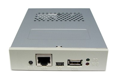
DiagnosisThere are status lights in the front of the USB Floppy, one red (marked N/U) and one green (marked FD). Together they can be used to help diagnose issues, with the following chart. Look for a BRIGHT green and red light, there are internal lights in the unit and so the green and red lights may appear dimly lit, but please do not be confused. It will be a very bright light. Red light means powerup successful or USB stick is currently being accessed. Green light means your host system is trying to access the “floppy” data.
Status Light Explanation
Data Errors
USB Floppy ModelsThe following table is a list of the popular USB Floppy models in current release.
 (C) 2009-2018 PLR Electronics |
||||||||||||||||||||||||||||||||||||||||||||||||||||||||||||||||||||||||||||||||||||||||||||||||||||||||||
USB Floppy Disk Drive